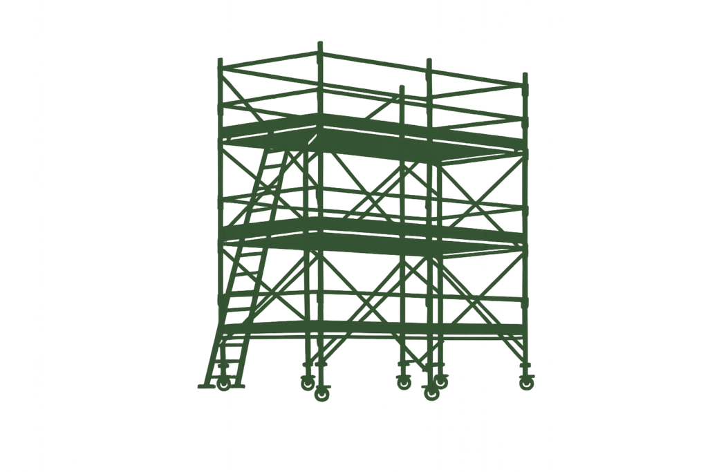
Work Out Scaffold Bays From the Total Run Length
A scaffold bay is the horizontal section between two adjacent standards. To estimate the number of bays along a straight elevation, divide the scaffold run by the preferred bay size and round the result up to the next whole bay. The calculator then redistributes the total run so you can see the exact dimension if every bay is made equal.
For example, a 17 metre run planned around 2 metre bays needs nine bays. Equalising the run produces bays of approximately 1.889 metres. If you instead keep full 2 metre bays, eight bays account for 16 metres and the final bay is 1 metre.
This free planning service is useful when setting out an elevation, preparing an early material take-off or giving a scaffolding contractor clearer dimensions for a quotation. It does not decide what bay length is structurally suitable.
Why the Calculator Shows Two Bay Layouts
A building elevation rarely divides perfectly by the bay dimension selected at the start of planning. Simply rounding the number of bays without considering the remaining distance can leave an awkward final section.
The calculator therefore shows two geometrical approaches. The equalised layout spreads the full run across the required number of bays. The preferred-size layout keeps as many bays as possible at the entered dimension and places the remainder in the last bay.
| Layout |
How it divides the run |
Useful for |
| Equalised bays |
Every bay receives the same calculated dimension. |
Seeing a regular geometric set-out. |
| Preferred bays + remainder |
Full preferred-size bays are used first, followed by the remaining distance. |
Checking how large the final short bay would be. |
Preferred Bay Size Is Not the Same as Maximum Bay Length
The number entered as a preferred bay size is only a planning target. It must not be treated as a generic safe maximum for all scaffolds. HSE scaffold guidance states that the scaffold contractor or designer should provide project information including maximum bay lengths, maximum lift heights, platform arrangements, load class and tie requirements.
A scaffold must either follow a recognised standard configuration or be supported by suitable design calculations. For tube and fitting scaffolds, NASC TG20 provides recognised configurations; TG30 provides corresponding guidance for system scaffolding. Proprietary system scaffolds also need to follow the relevant manufacturer’s instructions.
For that reason, the calculator deliberately avoids recommending a “best” bay length. It works from the dimension you enter and leaves the suitability decision to the applicable compliance sheet, manufacturer information or competent scaffold design.
Tube and Fitting Bays and System Scaffold Bays Are Not Identical Planning Problems
Tube and fitting scaffolding offers flexibility in where standards and ledgers are positioned, subject to the configuration or design being followed. A calculated equal bay dimension can therefore be useful when exploring how a measured run could be divided.
System scaffolding is different because bay lengths are commonly governed by the manufacturer’s available ledger and transom sizes. A result such as 1.86 metres may be mathematically neat but unusable if the chosen system has no compatible component at that length. On system scaffold projects, use this tool for initial geometry only and then map the result to manufacturer-approved component sizes.
Bay Count Helps With Scaffold Material Planning
Once the number of bays is known, it becomes easier to understand how often components repeat along the scaffold. Each additional bay changes the number and position of standards, ledgers, transoms and platform sections required, while the number of bay lines is normally one more than the number of bays on a straight run.
For the next stage of planning, the scaffolding board calculator can help estimate platform boards, while the scaffolding weight calculator addresses a different part of the material-planning process. Structural loading should be considered separately using the scaffolding load calculator and, where appropriate, project-specific design information.
Measure Each Straight Scaffold Elevation Separately
Do not combine front, side and rear elevations into one long theoretical run if the scaffold changes direction. Corners, returns, projections, access bays and changes in building line can alter where standards need to be positioned.
Measure each straight section from its intended start point to its finish point and calculate the bays separately. This produces a clearer set-out and makes unusually short finishing bays easier to identify before materials are allocated.
If scaffold height is also being planned, use the separate scaffolding height calculator. Bay length and scaffold height answer different questions and should not be merged into one simplified dimension.
Use the Bay Result as a Planning Check, Not an Erection Instruction
The calculator provides dimensions, not a scaffold design. It does not assess loading, wind, ties, bracing, ground conditions, platform duty, sheeting, access, bridges, loading bays or whether a proposed arrangement falls inside a recognised configuration.
HSE guidance requires scaffolding to be planned, erected, altered and dismantled by competent people. Before the bay layout is used on site, compare it with the compliance sheet, drawing, manufacturer instructions or bespoke design that applies to the actual scaffold.