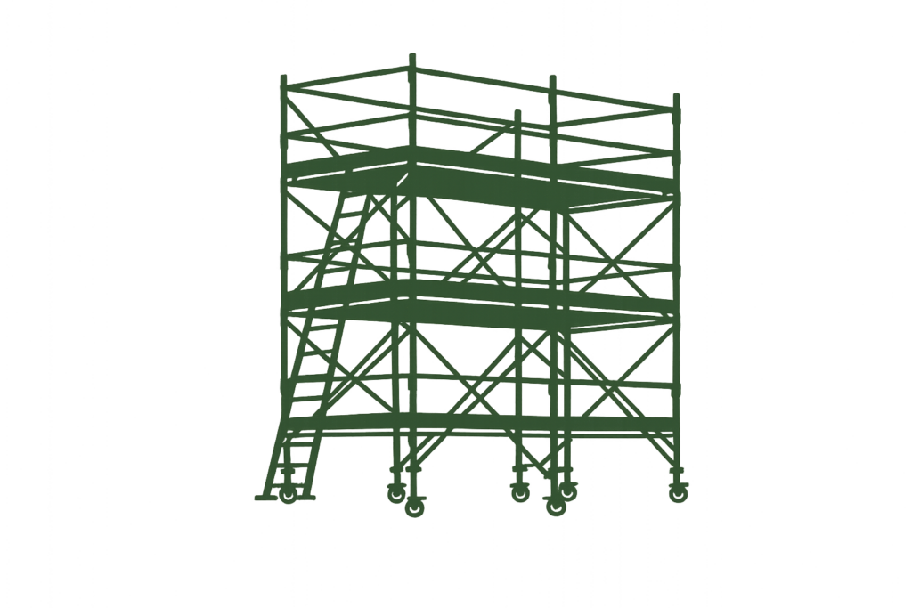
What the Scaffold Tie Calculator Is Designed to Show
A scaffold tie estimate is most useful at the planning stage, when you know the approximate size of the scaffold but still need a quick idea of the number of tie positions that a chosen grid could create. The calculator works from the scaffold face rather than the building footprint, so the two measurements that matter first are the overall run length and the scaffold height.
You can then enter the horizontal and vertical spacing you want to assess. The result converts that grid into an estimated number of tie positions. It also shows the approximate scaffold face area, the selected tie duty and whether the scaffold is open, netted or sheeted.
The figure is deliberately presented as an estimate. Scaffold stability cannot be decided from length and height alone, and the final arrangement must follow the applicable compliance sheet or a design prepared for the actual scaffold.
Measure the Elevation, Not the Floor Area
For tie planning, start with the elevation that will be tied back to the supporting structure. Measure the full scaffold length along that face and the total erected height. A scaffold running around several sides of a property should not automatically be treated as one flat rectangle, because corners, returns and changes in geometry can affect how stability is provided.
If the scaffold has several distinct elevations, it is usually clearer to estimate each face separately and then compare the combined total with the final design information. That keeps the calculation understandable and makes it easier to identify where a return, opening or unusually exposed section may need separate consideration.
Tie Spacing and Tie Duty Are Different Things
Tie spacing describes where ties are positioned across the scaffold. Tie duty describes the working load that the tie arrangement must be capable of resisting. A closer grid does not automatically prove that each individual tie has enough capacity, and selecting a higher tie duty does not automatically allow ties to be placed further apart.
For UK scaffolding work, the required pattern and duty should be taken from the relevant compliance sheet or design. NASC guidance recognises light, standard and heavy duty tie classifications, but the correct class for a particular scaffold depends on the configuration and design requirements rather than a calculator choice alone.
Why Netting and Sheeting Need Extra Attention
Cladding changes the way wind acts on a scaffold. Debris netting, monoflex, shrink wrap and other sheeted arrangements can increase the forces that have to be transferred through the scaffold and its ties. That means a tie layout that may be suitable for an open scaffold should not simply be copied onto a clad scaffold.
The calculator records whether the scaffold is open, netted or sheeted so the result carries the appropriate warning. It does not try to replace a wind assessment. Where cladding materially changes the loading, use the tie requirements stated on the relevant compliance sheet or obtain a bespoke scaffold design.
The Building Behind the Scaffold Matters
A tie is only useful if the connection and the supporting structure can safely resist the load being transferred into them. Brickwork, blockwork, concrete, steelwork and other substrates behave differently, while old, damaged or uncertain masonry can make anchor selection and testing especially important.
This is why tie planning should include more than a quantity. The fixing method, anchor specification, edge distances, base material, installation procedure and any proof or preliminary testing requirements all need to be considered. If those details are not already defined, the tie count should be treated as an early estimating figure only.
When a Simple Tie Grid Is Not Enough
Regular rectangular elevations are the easiest situations to estimate. Large openings, gantries, cantilevers, loading bays, bridges, temporary roofs, unusual returns and partially tied structures can all change the stability strategy. The same applies where normal tie positions are unavailable because of windows, cladding systems, weak substrates or restrictions imposed by the client.
For these scaffolds, a simple grid can still help with an early material allowance, but it should not be used as the erection instruction. The final arrangement needs to show where ties are actually positioned and what duty each connection must achieve.
Six Checks to Make Before Relying on a Tie Estimate
A useful tie calculation starts with the right project information. These six checks help separate a rough quantity from the information needed for a safe scaffold arrangement.
Scaffold Elevation
Length × Height
Measure the tied face
Split complex elevations where needed
Proposed Tie Grid
Horizontal × Vertical
Editable spacing
Use the design requirement, not guesswork
Cladding Condition
Open / Netted / Sheeted
Wind exposure matters
Cladding can change tie demand
Tie Duty
Working Load
Specified in kN
Confirm the class for the scaffold
Fixing Substrate
Anchor or Tie Method
Check the structure
Testing may be required
Design Status
Compliance or Bespoke
Use the correct document
Final pattern comes from design information
How the Estimate Is Calculated
The calculator divides the scaffold length by the horizontal tie spacing and the scaffold height by the vertical spacing, rounding the result to whole tie lines and rows. If the end-position allowance is selected, an additional vertical line is included to give a simple allowance for ties near the ends of the elevation. The horizontal lines and vertical rows are then multiplied to produce the estimated tie quantity.
This method is intentionally transparent. You can change the proposed spacing and immediately see how the quantity changes. It is useful for comparing preliminary layouts, but it does not model wind pressure, local tie forces, eccentricity, façade openings, corner effects, anchor capacity or the detailed rules contained in a compliance sheet.
TG20, TG30 and Bespoke Scaffold Design
Tube and fitting scaffolds that fall within recognised standard configurations can be supported by the appropriate TG20 compliance information. System scaffolds may be covered by TG30 or by the manufacturer’s design information, depending on the arrangement. Where a scaffold falls outside the available standard solution, design input is required.
The important point for tie planning is that the compliance sheet or design is the controlling document. It should identify the tie pattern, required tie load and any conditions that have to be met for the scaffold to remain within the stated configuration.
Anchors, Through Ties and Other Tie Methods
Scaffold ties can be achieved in different ways depending on the building and the design. A through tie uses an opening or suitable part of the structure to form a positive connection. Anchor ties rely on a fixing installed into an appropriate substrate. Other arrangements can be used where they are permitted by the design and installed correctly.
Do not choose a fixing solely because its advertised capacity appears higher than the selected tie duty. The base material, anchor type, installation quality and testing regime all affect the connection. Where the substrate is uncertain, the required test procedure should be established before relying on the anchor.
Use the Result for Planning, Then Verify It
A tie estimate can help a scaffolder or client discuss material quantities, access requirements and likely fixing locations before work starts. It can also highlight the effect of changing the scaffold size or proposed grid. For related checks, the scaffolding load calculator can be used separately to consider platform loading rather than tie quantity.
Before erection, compare the estimate with the actual scaffold documentation. If the compliance sheet or design shows a different tie arrangement, the documented requirement takes priority. Never remove, move or omit a tie simply to match the calculator result.