Scaffolding Material Calculator

Estimate the core materials for a straight tube-and-fitting scaffold from its length, height, bay size, lift height and platform width. The calculator works out scaffold face area and an indicative take-off for tubes, boards, standards, ledgers, transoms, braces, fittings and base plates.

Tube & Fitting Planning Tool

Scaffolding Material Calculator

Enter the main dimensions of a straight independent scaffold to produce an indicative core-material take-off. The calculator rounds the layout up to complete bays and lifts, then estimates tube length, boards, standards, ledgers, transoms, façade braces, fittings and base plates.

Horizontal run of the scaffold elevation.
Overall height to the top scaffold lift/grid.
Nominal spacing between adjacent standards along the run.
Vertical spacing used to build the calculation grid.
Used for board coverage and indicative transom tube length.
How many lift levels you want included in the board estimate.
Advanced material assumptions
Used only for an equivalent stock-length figure, not as a cutting plan.
Change this if your board or platform system uses a different width.
Converts required board metres into an indicative whole-board quantity.
Planning assumption only. Use the actual TG20/design arrangement for a real scaffold.
Applied to stock-tube equivalent, boards and fittings. Geometry-based member counts remain unchanged.
Measured scaffold face area
72.0 m²
Material grid: 6 bays × 3 lifts
Full bays6
Full lifts3
Grid run12.0 m
Grid height6.0 m
Core material estimate
Tubes—
Boards—
Standards—
Ledgers—
Transoms—
Façade braces—
Fittings—
Base plates—
The result is an early quantity estimate for a simple straight independent tube-and-fitting scaffold. It is not a scaffold design or erection schedule.
Important: ties, guard rails, toe boards, sole boards, access equipment, loading bays, beams, fans, hop-ups, gates, sheeting/netting and specialist components are not included. Confirm all quantities against the scaffold design, TG20 compliance sheet or competent designer's drawing before ordering or erecting equipment.

Turn Scaffold Dimensions Into an Early Material Take-Off

A scaffolding material take-off starts with the geometry of the scaffold rather than a single square-metre figure. Length determines how many bays are needed, height determines the number of lifts, and platform width changes the amount of boarding and the cross-scaffold tube requirement.

This calculator converts those measurements into a practical first estimate for a simple straight independent tube-and-fitting scaffold. It also shows the measured scaffold face area, making it useful when comparing the material requirement with other planning tools such as the scaffolding area calculator.

The result should be treated as an estimating aid. Real scaffolds can require additional members for ties, edge protection, access, returns, loading bays, bridges, pavement lifts, rakers, sheeting and other site-specific details.

How the Scaffolding Material Calculator Uses Your Measurements

The calculator builds a simple bay-and-lift grid. If the entered length or height does not divide exactly by the selected spacing, it rounds up to a complete bay or lift for the material calculation. This avoids treating a partial final section as though it needs no supporting members.

Input What it changes
Scaffold length Bay count, ledgers, standards, platform run and board requirement.
Scaffold height Lift count, standard tube length and vertical extent of the scaffold.
Bay size Number of bays, ledger members and the geometry used for the brace estimate.
Lift height Number of horizontal scaffold levels and the quantity of repeated members.
Platform width Board coverage across the working platform and indicative transom tube length.

What Materials Does the Calculator Estimate?

The output separates the main components so that the result is easier to check than a single combined quantity.

Tubes and Standards

The tube total combines the core linear metres represented by standards, ledgers, transoms and the indicative façade braces. Standards are the vertical uprights. The calculator also converts total tube metres into an equivalent number of the stock-tube lengths entered in the advanced settings, but this is not a cutting schedule.

Ledgers and Transoms

Ledgers run horizontally along the scaffold elevation and connect the standards. Transoms run across the scaffold width. The model counts these members from the number of bays and lifts, then uses the chosen bay size and platform width to contribute to the tube-length estimate.

Boards

Boarding is calculated separately because not every lift is necessarily boarded. Enter the number of boarded lifts you want to include. The calculator uses the platform width, board width, scaffold run and board length to create an indicative whole-board quantity.

Braces, Fittings and Base Plates

Façade bracing is included as an editable planning assumption rather than a fixed design rule. The fitting figure covers the basic connections represented by the model, while base plates are counted from the two rows of standard positions.
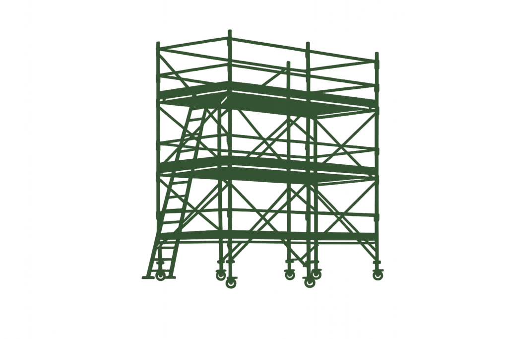
Core Quantities Shown in the Result

The calculator keeps geometry-based member counts separate from the optional spare-material allowance so you can see what the dimensions create before allowing for stock and handling.

Scaffold Grid

Bays × Lifts
Rounded to whole sections
Shows the calculation layout

Tube Requirement

Linear Metres
Core framework members
Plus stock-length equivalent

Board Requirement

Whole Boards
Selected boarded lifts
Based on editable board size

Framework Members

Standards & Ledgers
Transoms and braces
Separated for checking

Connections

Core Fittings
Basic represented joints
Specialist fittings excluded

Ground Contact

Base Plates
One per standard position
Sole boards not included

Why a Material Estimate Is Different From a Scaffold Design

A material calculator answers a quantity question. A scaffold design answers whether a proposed arrangement has adequate strength, rigidity and stability for the site, loading and intended use. Those are not interchangeable tasks.

The UK Health and Safety Executive states that scaffolds should either follow a recognised standard configuration, such as NASC TG20 for tube-and-fitting scaffolds, or be designed by calculation by a competent person where the scaffold falls outside recognised configurations. HSE also identifies details such as scaffold height and length, the number of boarded lifts, intended use and working loads as information that may be needed during planning. See the HSE scaffolding guidance.

That is why this tool deliberately does not calculate tie patterns, duty ratings or structural capacity. For those early-stage questions, use the scaffolding tie calculator and scaffolding load calculator as separate planning aids, then confirm the actual scaffold against the recognised configuration or design.

Where Real Scaffold Quantities Commonly Increase

A straight elevation is the simplest material take-off. Real projects often contain features that add components without greatly changing the measured face area.

  • Returns and corners create extra standards, ledgers, transoms and fittings.
  • Additional boarded lifts increase the board requirement and may alter loading considerations.
  • Access towers, ladder bays and staircase systems add dedicated components.
  • Loading bays, bridging beams, cantilevers, rakers and protection fans sit outside this basic model.
  • Guard rails, toe boards, ties and sole boards are essential project items but are not included in the core quantity result.
  • Sheeting or debris netting can change the structural demands on a scaffold and should not be added simply because the material quantity is known.

If the project includes enclosure material, calculate that separately with the scaffolding sheeting calculator. For board-only planning, the scaffolding board calculator provides a more focused calculation.

Example: Building a First Material Estimate

Suppose a scaffold elevation measures 12 metres long and 6 metres high, using 2 metre bays and 2 metre lifts. The calculator identifies six full bays and three full lifts. That gives a measured face area of 72 m² before considering the depth of the scaffold or any returns.

If the platform width is 0.9 metres, the cross-scaffold members and boarding are then estimated from that width. The number of boarded lifts is entered separately, because a three-lift scaffold does not automatically mean that all three lifts are fully boarded.

This separation is useful when comparing alternatives. Changing a 2 metre bay to a shorter bay may leave the face area unchanged while increasing the number of standards, ledgers, transoms, base plates and fittings.

Before Ordering, Hiring or Allocating Scaffold Equipment

Use the result as a checkable starting point and then compare it with the real scaffold arrangement. Confirm the number of elevations, returns, internal standards, boarded lifts, access bays and specialist features before turning the estimate into an order list.

Tube length also needs a cutting and stock plan. A total of 150 linear metres does not mean that any combination of 150 metres of tube will fit the required standards, ledgers, transoms and braces. Available lengths, joints, reusable offcuts and transport constraints can change the number of physical tubes required.

For transport and handling planning, take the confirmed component list into the scaffolding weight calculator. If you are still establishing the required vertical extent, use the scaffolding height calculator before finalising the take-off.

Scaffolding Material Calculator FAQs

It provides an indicative quantity of core materials for a simple straight independent tube-and-fitting scaffold. Using the entered length, height, bay size, lift height and platform width, it estimates scaffold face area, tube metres, boards, standards, ledgers, transoms, façade braces, fittings and base plates. It is a planning take-off rather than a structural design.

The calculator divides the scaffold length by the selected bay size and rounds the result up to a whole bay. Rounding up matters because a partial final section still needs standards and connecting members. The resulting full-bay run is shown separately from the measured building or scaffold length.

The scaffold height is divided by the chosen lift height and rounded up to a whole lift. The calculator then uses that full lift grid when estimating ledgers, transoms and vertical tube. Actual lift positions must follow the scaffold design, recognised configuration or system manufacturer guidance.

The core tube figure combines the calculated vertical standard length, ledgers, transoms and indicative façade braces. It does not include guard rails, ties, ladder beams, loading bays, rakers, protection fans, hop-ups, gates or other project-specific tube requirements.

Platform width affects the amount of boarding and the indicative length of transoms in this simplified take-off. A wider working platform normally needs more board coverage and longer cross-members. The entered width is a material-planning input, not confirmation that a platform is suitable for a particular task.

The tool converts the platform width into a number of board-width positions, multiplies that by the rounded scaffold run and the selected number of boarded lifts, then converts the resulting board metres into whole boards using the board length entered under advanced assumptions. A real bay-by-bay board layout can require a different quantity.

Standards are the vertical uprights. Ledgers run horizontally along the length of the scaffold and connect the standards. Transoms run across the scaffold width and help form and support the working platform. These members work together as part of the scaffold framework.

The calculator uses the editable brace interval in the advanced assumptions and creates an indicative diagonal member count from the number of bays and lifts. This is only a quantity-planning assumption. The actual bracing arrangement must come from the applicable TG20 compliance information, manufacturer guidance or a competent scaffold design.

The fitting estimate includes basic couplers for the calculated ledgers, transoms and façade braces, plus sleeve couplers where the simplified standard calculation needs more than one tube section vertically. It excludes tie fittings, guard-rail fittings, specialist couplers, jointing details and accessories not represented by the core model.

No. Tie number, type and position depend on the scaffold configuration, loading, façade, sheeting or netting, exposure and design requirements. Use the separate scaffolding tie calculator for early planning, then confirm the final tie pattern from the TG20 compliance sheet or scaffold design.

Use it as a first-pass take-off, not as the final order list. Before hiring or purchasing equipment, compare the result with the actual scaffold drawing, bay arrangement, boarded lifts, access provision, tie pattern, edge protection, ground conditions and any specialist features.

The component logic is written for a basic tube-and-fitting independent scaffold, so it should not be treated as a system-scaffold bill of materials. Ringlock, Cuplock and other proprietary systems use manufacturer-specific standards, ledgers, decks, braces, nodes and allowable configurations.

No. It does not produce a TG20 compliance sheet and does not confirm structural adequacy. HSE guidance states that scaffolds should either follow a recognised standard configuration, such as NASC TG20 for tube-and-fitting scaffolds, or be designed by calculation by a competent person when they fall outside recognised configurations.

Returns, corners, stepped elevations, pavement lifts, internal standards, loading bays, bridges, cantilevers, beams, rakers, extra boarded lifts, guard rails, toe boards, ties, access towers, sheeting and restricted tube lengths can all increase the actual quantity. Cutting and stock availability can also create extra waste.

Measure the scaffold run and required height, decide the intended bay and lift arrangement, identify the platform width and count the lifts that will actually be boarded. If different elevations use different dimensions, calculate them separately rather than averaging them into one rectangle.

Use this calculator for preliminary material planning only. The quantities do not replace a TG20 compliance sheet, manufacturer’s instructions, scaffold design, competent-person assessment or erection plan. Check the final component list against the actual scaffold configuration before materials are ordered, delivered or erected.